- 您现在的位置:买卖IC网 > Sheet目录332 > IRPLLED7 (International Rectifier)IC MOSFET DRIVER
�� �
�
�IRS2980S�
�being� used� in� dim� mode� place� a� capacitor�
�CDIM� from� the� ADIM� pin� to� COM� and� keep�
�the� capacitor� as� close� to� the� IC� as� possible�
�with� the� shortest� possible� traces.�
�4)� If� the� IRS2980S� is� being� used� in� non-dimming�
�mode� the� RAMP� pin� can� be� connected� to�
�COM.� If� it� is� being� used� in� dimming� mode�
�CRAMP� should� be� located� close� to� the� IC� with�
�the� shortest� possible� traces� to� the� RAMP� pin�
�and� COM.�
�5)� Connect� IC� COM� to� power� GND� at� one�
�connection� only.� Do� NOT� route� power� GND�
�through� the� programming� components� or� IC�
�COM.�
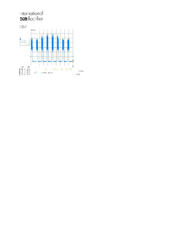
�Figure� 5:� LED� current� during� dimming.�
�The� dimming� level� can� also� be� controlled� from� a�
�digital� input� by� replacing� CRAMP� with� a� 68k�
�resistor.� This� sets� a� DC� threshold� at� the� RAMP�
�pin� to� approximately� 1V� so� that� a� logic� level� PWM�
�dimming� control� signal� can� be� applied� to� the� ADIM�
�pin� to� directly� switch� the� output� on� and� off.�
�PCB� Layout� Guidelines�
�Proper� care� should� be� taken� when� laying� out� a�
�PCB� board� ensure� correct� functionality� of� the�
�IRS2980S.� Transients� caused� by� high� dV/dt�
�during� switching� could� potentially� cause� some�
�false� triggering� of� the� hysteretic� circuit� therefore� a�
�small� filter� comprising� RF� and� CF� is�
�recommended.� CF� should� be� located� close� to� the�
�IC� pins� with� the� trace� from� HV� to� RCS� and� the�
�traces� from� RCS� to� CS� through� RF� kept� as� short�
�as� possible.� The� 0V� load� return� power� ground�
�should� be� connected� to� the� IC� COM� pin� and� at� a�
�single� point� to� avoid� ground� loops.� The� values� of�
�RF� and� CF� are� normally� chosen� to� provide� noise�
�filtering� without� adding� excessive� delay� to� the�
�circuit,� however� in� some� case� these� are�
�deliberately� made� larger� to� lower� the� running�
�frequency� as� this� reduces� switching� losses� and�
�ICC� current.�
�The� following� guidelines� should� be� followed� during�
�PCB� board� layout:�
�1)� Place� VCC� supply� decoupling� capacitor�
�(CVCC)� as� close� as� possible� to� the� VCC� and�
�COM� pins.�
�2)� Place� high� side� decoupling� capacitor� (CVF)� as�
�close� as� possible� to� the� HV� and� VS� pins.�
�3)� If� the� IRS2980S� is� being� used� in� non-dimming�
�mode� connect� the� ADIM� pin� to� VCC.� If� it� is�
�www.irf.com�
�14�
�?� 2011� International� Rectifier�
�发布紧急采购,3分钟左右您将得到回复。
相关PDF资料
IRPP3637-06A
BOARD REF DESIGN POWIR+
IRS2001MPBF
IC DRIVER HIGH/LOW SIDE 16MLPQ
IRS2001SPBF
IC DRIVER HI/LO SIDE 200V 8-SOIC
IRS2003STRPBF
IC DRIVER HALF-BRIDGE 8-SOIC
IRS2004PBF
IC DRIVER HALF-BRIDGE 8-DIP
IRS2011PBF
IC DRIVER HI/LO SIDE 8-PDIP
IRS2101SPBF
IC DRIVER HIGH/LOW SIDE 8-SOIC
IRS2103SPBF
IC DRIVER HALF-BRIDGE HV 8-SOIC
相关代理商/技术参数
IRPLLNR1
制造商:未知厂家 制造商全称:未知厂家 功能描述:
IRPLLNR2E
功能描述:KIT BALLAST LINEAR INT 230VAC RoHS:否 类别:编程器,开发系统 >> 过时/停产零件编号 系列:- 标准包装:1 系列:- 类型:MCU 适用于相关产品:Freescale MC68HC908LJ/LK(80-QFP ZIF 插口) 所含物品:面板、缆线、软件、数据表和用户手册 其它名称:520-1035
IRPLLNR2U
功能描述:BALLAST 32W/T8 120V AC IR21571 RoHS:否 类别:编程器,开发系统 >> 过时/停产零件编号 系列:- 标准包装:1 系列:- 类型:MCU 适用于相关产品:Freescale MC68HC908LJ/LK(80-QFP ZIF 插口) 所含物品:面板、缆线、软件、数据表和用户手册 其它名称:520-1035
IRPLLNR3
制造商:IRF 制造商全称:International Rectifier 功能描述:Universal Input Linear Fluorescent Ballast using the IR2167
IRPLLNR4
功能描述:BALLAST UNIV INP FLUOR IR2166 RoHS:否 类别:编程器,开发系统 >> 过时/停产零件编号 系列:- 标准包装:1 系列:- 类型:MCU 适用于相关产品:Freescale MC68HC908LJ/LK(80-QFP ZIF 插口) 所含物品:面板、缆线、软件、数据表和用户手册 其它名称:520-1035
IRPLLNR5
功能描述:电源管理IC开发工具 Uni Inpt Lin Fluor Ballast 54W TL5 Lamp RoHS:否 制造商:Maxim Integrated 产品:Evaluation Kits 类型:Battery Management 工具用于评估:MAX17710GB 输入电压: 输出电压:1.8 V
IRPLLNR7
功能描述:电源管理IC开发工具 Flourescent Ballast Using IRS2166DPBF RoHS:否 制造商:Maxim Integrated 产品:Evaluation Kits 类型:Battery Management 工具用于评估:MAX17710GB 输入电压: 输出电压:1.8 V
IRPLMB1E
功能描述:KIT DESIGN BALLAST 220VAC RoHS:否 类别:编程器,开发系统 >> 过时/停产零件编号 系列:- 标准包装:1 系列:- 类型:MCU 适用于相关产品:Freescale MC68HC908LJ/LK(80-QFP ZIF 插口) 所含物品:面板、缆线、软件、数据表和用户手册 其它名称:520-1035